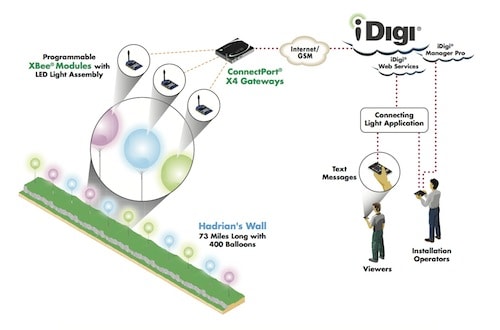
Connecting Light System Diagram
Here’s how the Connecting Light system is created from Digi equipment for the 73-mile-long installation of 400 giant illuminated balloons on Hadrian’s Wall in northern England. The huge network will go live tonight for an crowd expected to bring traffic along the 80-mile World Heritage site to a crawl as thousands of spectators flock to the interactive event. Connecting Light is a perfect example of a large-scale system for centrally controlling remote devices—the same advanced infrastructure that hospitals use to monitor patient ventilators, infusion pumps or dialysis machines, and that forward-thinking power utilities use to network their entire grid.
The technology required for Connecting Light was assembled by Digi Professional Services—my same colleagues who network dynamic message signs along highways, smart thermostats for utility networks and positive train control systems for railroads. Putting all these different devices online is arguably the next big revolution for the Internet. Organizations are starting to demand visibility to their remote assets along with centralized control for everything out in the field as their competitors begin benefitting from the systems currently being put in place. It’s an exciting time to be involved with this stuff!
The diagram above shows how Programmable XBees, ConnectPort GSM mobile routers and the iDigi Device Cloud all work together to form a reliable backbone behind a breathtaking artwork that spans England’s coasts.It is also available as a PDF.


I love this project. Thanks for sharing information on it. I’m curious how you are setting RGB values. Are you using PWM? Which version of the xBee radio are you using in this project?
This project used the Programmable XBee, and it did indeed send PWM values to three channels of LED drivers inside each balloon.