Wireless Communication with XBee Radios |
|||
Practical Example (April, 2006) |
|||
|
*** This is an older example. For up-to-date information, focused on the Series 2 hardware, see the book, Building Wireless Sensor Networks: with ZigBee, XBee, Arduino, and Processing ***
Minimum parts needed: (see Tom Igoe's parts list for additional details)
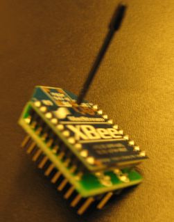
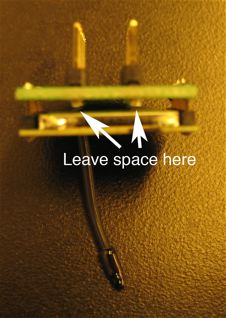
Step 1: Solder the XBee RF Module to the PCB breakout board as shown. The white silkscreened lettering should face downward, away from the XBee Module. Be sure to leave enough space so that the headers do not touch the back of the module.
XBee soldered to custom breakout board. Be sure to leave enough space between the
|
|||
| Step 2:
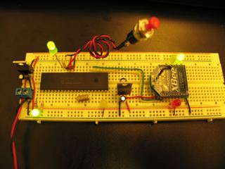
Set up two breadboards with a PIC on each. You'll need to add a 3.3 Volt regulator to each board, for powering the XBee radios. The 3.3V regulator used in this example is arranged (from left to right) Ground-Output-Input, which is different from the 5 Volt one.
PIC18F452 running on 5 Volts. XBee running on 3.3 Volt regulator at center of breadboard. |
|||
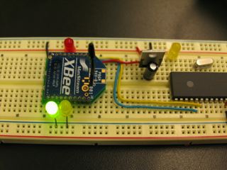
| Step 3:
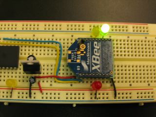
Connect 3.3 Volt power to pin 1 of the XBee, ground to pin 10, RC7 from the PIC to pin 2 and RC6 to pin 3 as shown. You may also want to add LEDs to pins 6, 13 and 15 for some status feedback.
XBee connected to 3.3 Volt power and common ground. The XBee tx pin is connected to rx on PIC, and XBee rx pin is connected to tx on PIC. |
|||
| Step 4:
Program one microcontroller using this sending code: ' serial out is on portc.6 'set a constant with the baudmode 9600-8-n-1-true (non-inverted):
true9600 con 84
' a byte to send out data:
                         thisByte var byte
' set portb.0 to input:
                         input portb.0
                         ' set portd.1 to output for status light:
                         output portd.1
configure: ' label to jump back to if configuration times out ' blink status light once on startup
High portd.1
pause 200
low portd.1
PAUSE 200
' for some reason it seems to help to send an arbitrary character first
                         ' then pause for the guard time before requesting command mode
                         serout2 portc.6, true9600, ["X"]
                         pause 1500
' put the XBee in command mode
                         serout2 portc.6, true9600, ["+++"]
' wait for a response from the XBee for 2000 ms, or start
                         ' over at the configure label if no valid response comes
                         SERIN2 portc.7, true9600, 2000, configure, [WAIT ("OK")]
' set the PAN (personal area network) ID number
                         ' this example uses 0x3330, but you'll want to choose your own
                         ' unique hexadecimal number between 0x0 and 0xFFFE
                         serout2 portc.6, true9600, ["ATID3330,"]
' set the Destination High to 0x0
                         ' to select 16 bit addressing mode. These addresses can
                         ' be assigned and changed by sending commands from a microcontroller
                         serout2 portc.6, true9600, ["DH0,"]
' set the Destination Low (16 bit address)
                         ' this example uses 0x0 for send and 0x1 for receive but you'll
                         ' want to choose your own hexadecimal numbers between 0x0 and 0xFFFE
                         serout2 portc.6, true9600, ["DL1,"]
' exit command mode
                         serout2 portc.6, true9600, ["CN",13]
' wait for a response from the XBee for 2000 ms, or start
                         ' over at the configure label if no valid response comes
                         SERIN2 portc.7, true9600, 2000, configure, [WAIT ("OK")]

main:
 ' read the switch:
   thisByte = portb.0
' convert it to a readable ASCII value, send it out the serial port:
serout2 portc.6, true9600, [DEC thisByte]
goto main Here is the same code for Arduino: XBee_Send_Example.pde |
|||
| Step 5:
Program the other microcontroller using this receiving code: ' serial out is on portc.6 'set a constant with the baudmode 9600-8-n-1-true (non-inverted):
true9600 con 84
' set a constant for timeout while waiting for serial input
                       timeout CON 2000
' a byte to receive data:
                       inByte var byte
' set portb.1 to output:
                       OUTPUT portb.1
                       ' set portd.1 to output for status light:
                       output portd.1
configure: ' label to jump back to if configuration times out ' blink status light once on startup
High portd.1
pause 200
low portd.1
PAUSE 200
' for some reason it seems to help to send an arbitrary character first
                       ' then pause for the guard time before requesting command mode
                       serout2 portc.6, true9600, ["X"]
                       pause 1100
' put the XBee in command mode
                       serout2 portc.6, true9600, ["+++"]
' wait for a response from the XBee for 2000 ms, or start
                       ' over at the configure label if no valid response comes
                       SERIN2 portc.7, true9600, timeout, configure, [WAIT ("OK")]
' set the PAN (personal area network) ID number
                       ' this example uses 0x3330, but you'll want to choose your own
                       ' unique hexadecimal number between 0x0 and 0xFFFE
                       serout2 portc.6, true9600, ["ATID3330,"]
' set the MY (16 bit address)
                       ' this example uses 0x0 for send and 0x1 for receive but you'll
                       ' want to choose your own hexadecimal numbers between 0x0 and 0xFFFE
                       serout2 portc.6, true9600, ["MY1,"]
' exit command mode
                       serout2 portc.6, true9600, ["CN",13]
' wait for a response from the XBee for 2000 ms, or start
                       ' over at the configure label if no valid response comes
                       SERIN2 portc.7, true9600, timeout, configure, [WAIT ("OK")]

main:
 ' get any incoming data:
   SERIN2 portc.7, true9600, timeout, nodata, [DEC inByte]
   ' light the LED if a 1 has been received
   if inByte == 1 THEN
   HIGH portb.1
   ' douse the LED if anything else was received
   ELSE
   LOW portb.1
   ENDIF

   nodata: ' label to jump to if no data was received

goto main
Here is the same code for Arduino: XBee_Receive_Example.pde |
|||
| Step 6:
Attach a switch to RB0 of the sending board, and an LED to RB1 of the receiving board. Close the switch and the LED should light up. |
|||
| Step 7:
Change your code so that there's a switch and light on both boards, and closing either switch lights the light on the other board. This should help familiarize you with how the radios communicate. |
|||
This page created by Rob Faludi |
|||