
THIS IS THE OLDER VERSION OF THE STACKER. PLEASE SEE THE NEWER VERSION HERE.
This new project creates XBee radio-sized components that can be “stacked” directly underneath the radio. Each Stacker will add additional features like microcontrollers and sensors for devices that already use the XBee’s 20-pin footprint. The goal is to create plug-and-play tools for prototyping new concepts that extend the popular radio’s feature set. A few iterations have created a prototype that works great!
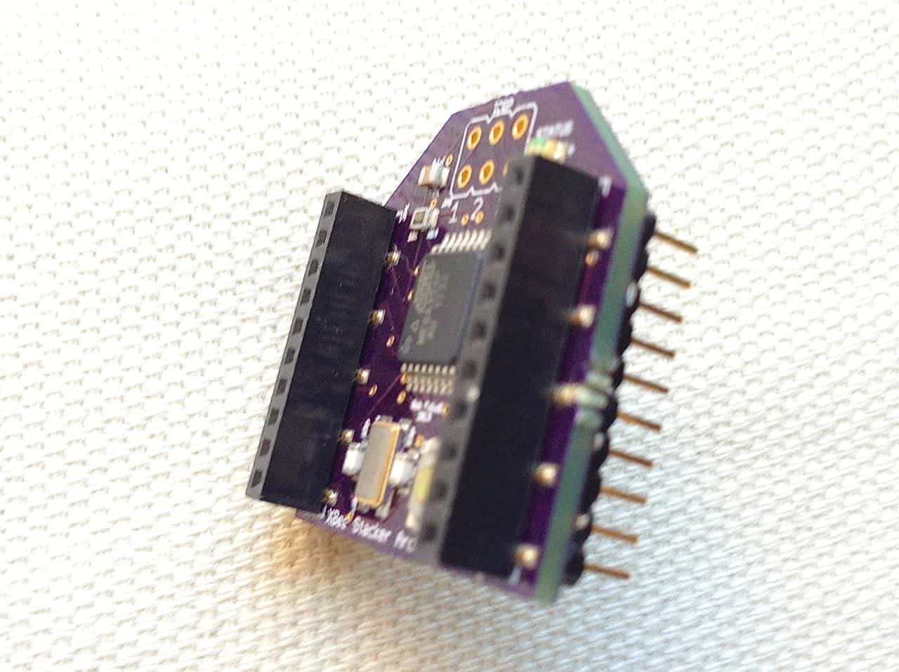
XBee Stacker Arduino
The first design is an Arduino-compatible board the size of an XBee that fits right underneath the radio, creating a Arduino-programmable XBee.


Features
-
I2C
-
SPI
-
scriptable interruption of:
-
all UART transactions
-
XBee reset
-
XBee pin sleep
-
-
pass-through of:
-
on/sleep indicator
-
association indicator
-
RSSI indicator
-
commissioning button
-
-
18 total digital i/o pins (14 Arduino, 4 XBee)
-
6 configurable as ADC analog inputs
-
4 configurable as PWM analog outputs
-
2 attachable interrupts
-
-
USB serial (via bootloader firmare) programming, using adaptor cable
-
wireless programming
-
ICSP for firmware access
-
EEPROM
-
multiple UARTs
-
Use of all Arduino libraries, e.g. servo, stepper, displays, capacitive sensing, rfid, sd cards etc.
Pinouts
Bottom of XBee Stacker Arduino:
| Base Pin | Physical Connection | Function |
| 1 | VCC | Power supply |
| 2 | Arduino D9 | Arduino software TX / PWM out |
| 3 | Arduino D8 | Arduino software RX |
| 4 | Arduino D12 | MISO (spi) / digital i/o |
| 5 | Arduino D2 | input for resets |
| 6 | XBee 6 | passthrough RSSI output |
| 7 | Arduino A4 | SCA (i2c) / analog input |
| 8 | Arduino A2 | analog input |
| 9 | Arduino D3 | input for pin sleep / PWM out |
| 10 | GND | GND |
| 11 | Arduino D11 | MOSI (spi) / digital i/o / PWM out |
| 12 | Arduino A0 | analog input |
| 13 | XBee 13 | passthrough on/sleep output |
| 14 | Arduino A3 | voltage reference / analog input |
| 15 | XBee 15 | passthrough assn output |
| 16 | Arduino A1 | analog input |
| 17 | Arduino D10 | SS (spi) / digital i/o / PWM out |
| 18 | Arduino D13 | SCLK (spi) / digital i/o |
| 19 | Arduino A5 | SCL (i2c) / analog input |
| 20 | XBee 20 | passthrough commissioning |
Top of XBee Stacker Arduino
| XBee Pin | Physical Connection | Function |
| 1 | VCC | Power supply |
| 2 | Arduino D0 | Arduino RX |
| 3 | Arduino D1 | Arduino TX |
| 4 | – | |
| 5 | Arduino D4 | control for resets |
| 6 | base 6 | passthrough RSSI output |
| 7 | – | – |
| 8 | – | – |
| 9 | Arduino D5 | control for pin sleep |
| 10 | GND | GND |
| 11 | – | |
| 12 | – | – |
| 13 | base 13 | passthrough on/sleep output |
| 14 | VCC | voltage reference |
| 15 | base 15 | passthrough assn output |
| 16 | – | – |
| 17 | capacitor | Arduino Reset (p1) via cap. |
| 18 | – | – |
| 19 | – | – |
| 20 | base 20 | passthrough commissioning |
Wireless Programming (Arduino XBee OTA)
This XBee Stacker can be programmed wirelessly using an Arduino setup first prototyped by me, then greatly improved by Limor Fried and later Shigeru Kobayashi. I’m borrowing it back now, thanks everyone!
Parts
2 – XBee 802.15.4
1 – XBee Explorer USB (or XBIB, or similar)
1 – USB cable
Configure Your XBees
XBees are factory configured for 9600 baud. The Arduino IDE typically sends programs (sketches) at 57600 baud. In addition, Arduino needs to reset the microcontroller on your remote board just before sending over a new sketch. This is cleverly accomplished by linking one of the base station’s hardware handshaking lines briefly to the reset line on the remote Arduino-based microcontroller. Here’s the chain of events:
- User clicks the upload button in the Arduino IDE. That’s it! The remaining steps happen automatically…
- Arduino (technically AVR Dude) opens the local serial port, automatically bringing the RTS line low.
- The RTS line is connected to pin DIO3 on the local XBee Explorer so that pin it goes low in tandem.
- The local, base station XBee has pin DIO3 configured as a digital input, and sends that low state to the remote XBee, the one plugged in to the XBee Stacker board.
- The remote XBee has pin DIO3 configured as a digital output, initially high. When it receives the low state from the base station XBee, its own DIO3 goes low too.
- DIO3 on the XBee Arduino Stacker is connected to the Arduino microcontroller’s reset line, but via a capacitor so only a burst of the low signal gets through, just enough to reset the microcontroller.
- The reset microcontroller goes into bootloader mode and accepts your new Arduino sketch over-the-air, then begins running that new sketch. All by itself and without wires!
Label one XBee “Base” and use X-CTU, CoolTerm or even the Arduino IDE’s Serial Monitor to give the “Base” XBee the following settings:
PAN ID 1234 -> ATID 1234 (I recommend that you choose your own unique PAN ID)
MY ID 1 -> ATMY 1
DESTINATION HIGH 0 -> ATDH 0
DESTINATION LOW 2 -> ATDL 2
BAUD RATE 57,600 -> ATBD 5
DIGITAL IO 3 input -> ATD3 3
CHANGE DETECT 3 on -> ATIC 8
Label the other XBee “Remote” and give it the following settings:
PAN ID: 1234 -> ATID 1234 (always match the “Base” radio’s PAN ID)
MY ID: 2 -> ATMY 2
DESTINATION HIGH: 0 -> ATDH 0
DESTINATION LOW: 1 -> ATDL 1
BAUD RATE: 57,600 -> ATBD 5
DIGITAL IO 3: output high -> ATD3 5
INPUT ADDRESS 1: -> ATIA 1
UART OUTPUT disable -> ATIU 0
If you are using CoolTerm or another Serial Terminal, use ATWR to save the configuration to your XBee’s firmware.
After you change their baud rate the radios will no longer respond at 9600 baud. Be sure to change the baud rate in X-CTU or CoolTerm to 57600 if you want to check or update their configurations.
Configure Your Hardware
The “Base” XBee’s DIO3 and RTS pins need to be connected together. If you are using an XBee Explorer, simply solder a jumper or wire between these two pins.

(If you are using Digi’s XBIB board or a different adapter, find the appropriate pins and then short them together either with some solder or with a bit of wire. Either method is reversible.)
Upload Sketches
Now you can start uploading Arduino sketches wirelessly! Simply:
- Connect your “Base” XBee into the modified XBee Explorer USB (or your own adapter) connect it to your computer with a USB cable.
- Stack your “Remote” XBee onto the XBee Arduino Stacker and provide it with power (a second Explorer or XBIB is an easy way to power it for tests).
- Select “Arduino Uno” in the Tools:Board menu and select the correct serial port from the Tools:Serial Port menu.
- Open the sketch you’d like to upload.
- Click the Upload button!
Should you get an error message, try again in case it’s just a one-time glitch. Next carefully recheck each connection and configuration item, one at a time. It’s very common to get something set wrong the first time you try this so go through it methodically and patience will pay off.
Schematics & Board Layout
XBee_Stacker_Arduino_schematic-1.1
XBee_Stacker_Arduino_board-1.1
Licensing
Not determined although open source hardware is top of my list right now.
Very nice project, do you think there is room to fit Humidity, Barometric pressure and Light sensors in the same board ?
many thanks.
Yes, it could probably be done. Although it might make more sense to do sensors as a separate board so that the selection of I/O and of microcontroller could be kept independent.