XBee Direct I/O with ADC

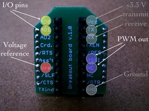
XBee radios can now record and output multiple channels of digital and analog data without using microcontrollers. The latest firmware (version 10A1) supports up to seven channels of analog input, nine channels of digital I/O and two channels of analog (pulse-width modulation) output. These will be great for creating small sensor modules or miniature output modules with low power and very low complexity.

Andrew Schneider and I cobbled a couple experimental modules together last weekend, and I recreated them for a demonstration to my Project Development Studio class. Here’s the presentation on XBee Direct that I gave to the class. Firmware updates can be performed with MaxStream’s X-CTU software, and you’ll certainly need to do this if your XBee’s were purchased before 2007.

Direct I/O should be considered for wearables, remote controls, toys, covert sensors, computational jewelry or anything airborne. Photos of the input and output circuits are below, along with the AT commands for this setup, with one analog (potentiometer) and one digital (switch) input, and the corresponding outputs (motor & LED):

INPUT MODULE:
ATID3456 –> PAN ID
ATMY1 –> my address 1
ATDL2 –> destination address 2
ATD02 –> input 0 in analog mode
ATD13 –> input 1 in digital in mode
ATIR14 –> sample rate 20 milliseconds (hex 14)
ATIT5 –> samples before transmit 5
ATWR –> write settings to firmware

OUTPUT MODULE:
ATID3456 –> PAN ID
ATMY2 –> my address 2
ATDL1 –> destination address 1
ATP02 –> PWM 0 in PWM mode
ATD15 –> output 1 in digital out high mode
ATIU1 –> I/O output enabled
ATIA1 –> I/O input from address 1
ATWR –> write settings to firmware


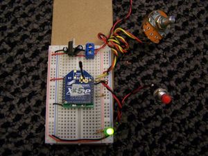
Input Module with Potentiometer and Switch


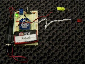
Output Module with Vibrator Motor and LED

92 Responses to “XBee Direct I/O with ADC”


  1. 1 adam synnott

    Hi, I just read this post and was fascinated by it. I would love to know more. is it possible for you to direct me to any information about xbee direct, as i’m interested in developing a wearable sensor system. any information would be much apreciated. cheers. adam

  2. 2 faludi

    Check the XBee User manual section 2.2.

  3. 3 Rushabh Sheth

    I was curious as to what you did with this project. I might be interested in this as I am interested in developing a link between to devices – One that receives audio input and transmits it to the other. The other device will receive the audio and activate a pager motor. Would you think you’d be able to help?

    Regards,
    Shubs

  4. 4 Shailendra

    Hi,
    I want to transmit adc data in multihop manner to base node. Can i do it in XBee?

    Regards,
    Shailendra

  5. 5 faludi

    To do multihop, you’ll want the XBee ZNet modules.

  6. 6 jupn

    Hi, dear faludi~

    “Xbee Series2(ZNET)” how to setup AT commands and use Direct I/O with ADC ?

    Regards,
    jupn.

  7. 7 Randy Goihl

    Hello..
    Sounds silly but how is the switch and LED connected ?

    Switch is D1 to ground or +3.3 ?

    LED is D1 Anode to ground or +3.3 ?

    Maybe a schematic of the input and output circuits

    Thank you

  8. 8 faludi

    Switch in this case was connected to +V and LED to GND. However it’s certainly possible to do it the other way around, and maybe preferable since you could take advantage of the internal pull-up resistors in the XBee for the switch.

  9. 9 btshil2000

    Hi,

    I am using X-CTU to program my XBee Pro modules. One is set up as a coordinator and the other as a End Point/Router. Unfortunately, I don’t have the option to change the address using ATMY in either the configuration screen or the Terminal screen. Trying to set ATMY in the terminal results in a error.

    Can you clarify which configuration the XBee Pro modules need to be in for the XBee to XBee communication to work?
    Thanks.

  10. 10 faludi

    For ZigBee (as opposed to 802.15.4) there’s no setting the ATMY addresses. Those are assigned dynamically. You can either address with the 64-bit address (and set with ATDH and ATDL or look up the 16-bit address with ATND.

  11. 11 btshil2000

    Thanks for your prompt response.

    The other issue that I ran into was getting errors with the ATIA command.

    In order to reproduce your project, do I need to use XBee Series 1 radios? Thanks.

  12. 12 faludi

    The 802.15.4 radios are definitely simpler if you want to simply make a pairing. Doing this with the ZNet 2.5 or ZB Pro radios is possible, but if you’re just doing two nodes then it adds complications without any direct benefits.

  13. 13 btshil2000

    Thanks. I have a couple of the 802.15.4 radios on order.
    Will let you know how it goes.

  14. 14 subin

    hi iam new to this site.Iam doing a project on zigbee based home automation system.Initially iam using two xbee modules to communicate.I could enter MY,DL,WR,etc commands.But iam getting error on ATD02,IR commands.Plz help me to sort it out the problem

  15. 15 faludi

    You need to upgrade the firmware on your radios. Check the Common XBee Mistakes page for more info.

  16. 16 Eth

    Thanks for the information. All I want to do is turn on an LED on the output module, using the X-CTU software how can I accomplish this? I’m sorry I’m new to all this but I’m willing to learn.

    Thanks,

  17. 17 faludi

    You want remote AT commands, used via API mode. If you have 802.15.4 radios you’ll also want firmware version 10CD.

    Not sure X-CTU is the best approach, that’s going to depend on your application.

  18. 18 JB

    Hello,

    I have two Digi Xbee-Pro 802.15.4 modules (with updated firmware) and am trying to send a command from the host (connected to the PC via USB) to the other module (not connected to the PC). The remote module is connected to a circuit that is designed to control a relay switch. I simply need the remote module to output a binary value of 1, when commanded by the host, or 0 when commanded by the host.

    I have spent hours attempting this using X-CTU but I receive countless errors. My programming knowledge is pretty slim, but I have used LabView quite extensively and VB just a little bit. What would be the best approach and any advice would be greatly appreciated.

    Thank you,

  19. 19 Arunbalaji

    Dear faludi,

    I need to send AT commands to Xbee modules using USART from the microcontroller. i am not able to enter into the command mode and receive data..

    here is the code..

    Transmitter:

    USART_Init();
    USART_vSendByte(‘X’);// send arbit character first

    // pause for 2s
    delayms();

    USART_vSendByte(‘+’);
    USART_vSendByte(‘+’);
    USART_vSendByte(‘+’);

    //pause for 2ms
    delayms();

    USART_vSendByte(‘A’);
    USART_vSendByte(‘T’);
    USART_vSendByte(‘I’);
    USART_vSendByte(‘D’);
    USART_vSendByteint(0×50);
    USART_vSendByteint(0x0D);

    USART_vSendByte(‘D’);
    USART_vSendByte(‘H’);
    USART_vSendByteint(0×00);
    USART_vSendByteint(0x0D);

    USART_vSendByte(‘D’);
    USART_vSendByte(‘L’);
    USART_vSendByteint(0×01);
    USART_vSendByteint(0x0D);

    USART_vSendByte(‘A’);
    USART_vSendByte(‘T’);
    USART_vSendByte(‘C’);
    USART_vSendByte(‘N’);
    USART_vSendByteint(0x0D);

    //pause for 2s
    delayms();

    while(1)

    {

    //transmitting data
    }

    At the receiving end…

    USART_InitTX();
    USART_vSendByte(‘X’);//some arbit data is sent first

    // pause for 2s
    delayms();

    //put xbee in command mode
    USART_vSendByte(‘+’);
    USART_vSendByte(‘+’);
    USART_vSendByte(‘+’);

    //pause for 2s
    delayms();

    USART_vSendByte(‘A’);
    USART_vSendByte(‘T’);
    USART_vSendByte(‘I’);
    USART_vSendByte(‘D’);
    USART_vSendByteint(0×50);
    USART_vSendByteint(0x0D);

    USART_vSendByte(‘M’);
    USART_vSendByte(‘Y’);
    USART_vSendByteint(0×01);
    USART_vSendByteint(0x0D);

    USART_vSendByte(‘A’);
    USART_vSendByte(‘T’);
    USART_vSendByte(‘C’);
    USART_vSendByte(‘N’);
    USART_vSendByteint(0x0D);

    //pause for 2000ms
    delayms();

    //receive data

    i followed your example on xbee with pic..
    please help..

  20. 20 faludi

    Are you delaying for two seconds?

  21. 21 faludi

    If you want to bring a pin high then for your setup remote AT commands (firmware 10CD) might be a good choice, but only if you are comfortable with programming. Otherwise, a microcontroller on the other end, receiving a serial command might be an easier method. Check out the Arduino system for an accessible environment for people newer to programming and electronics.

  22. 22 Sujith

    Hi faludi…

    I m using xbee module and hav designed my own board…. when i connect with xctu sw… it shows that the firmware version is 1084…

    i cud not configure my xbee pins as i/o or adc… when i type command atd0 3 it is showing ERROR… cud u help on that……..

    plz……………

    regrds,

    Sujith

  23. 23 faludi

    This is a very common problem. In fact it’s the first item on myCommon XBee Mistakes page: “Not using the latest firmware (especially if ATD0 or ATIR is giving an error).” Use X-CTU to upgrade the firmware to version 10A5 or 10CD and the error will go away.

  24. 24 HARAN

    hi
    i wish to send AT commands using HyperTerminal. ATID,ATMY,etc are working well but not working for ATD0. Is there any idea without x-ctu.

  25. 25 faludi

    You must use X-CTU to upgrade the firmware. This is a free download from Digi, and you can contact them for support if you need help.

  26. 26 David

    I would like to make an ultra-low power Xbee sensor/transceiver in which I can pulse the sensor instead of having it on all the time. As it appears in your picture, the potentiometer is always connected to the battery source, draining the energy. The idea would be: Every x seconds, turn the XBEE on, turn digital output to high to turn on sensor, take x samples with ADC, go to sleep.

    Is it possible to do this with X-CTU?

    Regards,

  27. 27 faludi

    Use the ON pin (13) to source voltage. This pin goes high when the radio is awake and low when it goes back to sleep.

  28. 28 Julio

    ATD02 –> input 0 in analog mode
    ATD13 –> input 1 in digital in mode

    i didn’t found this AT commands,D2 put a 0 and in D3 put a 1, or what??
    Thanx

  29. 29 faludi

    That would be ATD02 and ATD13. The D0 and D1 identify the pins. The 2 sets the pin to analog mode. The 3 sets the pin to digital input mode. Check the user guide for more details on this.

  30. 30 Liu

    i am not sure what do you mean by upgrade firmware? do you mean check “always upgrade firmware” box in the modem configuration tab? need i connect xbees to my computer when upgrading? basically i want use one xbee to receive analog signal and convert the signal to digital and transmit to the other xbee wirelessly. then the receiver xbee give the digital signal to a basic stamp. so after give xbee AT commands the transmitter xbee should be working without a mcu right? do i need to write specific code for basic stamp? cos previously i program basic stamp using “SERIN” command but couldn’t work..what pins should i connect?e.g. RX TX? i am totally new…really hope you can help thanks in advance!

  31. 31 faludi

    There’s several good tutorials on the net:

    Digi

    LadyAda

    SquidBee

    MakingThings

  32. 32 Liu

    now i am quite clear with the upgrading. but how to enable built-in adc and how to connect the pins? do you think the idea in my last post is possible?

  33. 33 xcool8

    creating a direct I/O with ADC in xbee for point to multi point? is it possible?

  34. 34 Pablo

    HI , I am using 2 xbee pro modules for a remote control application , the problem I have is when the modules connect (red led in adafruit adapter) , all the output (d0 to d4 ; programed as do low) go hi (+5v) , when i press the switch on the other side (di0 to di4) the output go low , i have a relay in each output (with a 2n2222 in the midle), I need to stay low until i press the switch , I think something is wrong in the programation of the modules?? , thanks
    Pablo

  35. 35 faludi

    Sounds like you need to wire your switches properly. The receiving XBee will always match the current state of the sending XBee. The Output Low and Output High settings merely indicate the default state _before_ information is received.

  36. 36 Victor

    Hi, Iam able to set my TX xbee io’s as inputs and my RX xbee io’s as outputs, however my outputs go from high to low when the buttons on my TX are pressed. I need the outputs to go from low to high, saves me having to put an inverter on the outputs.I tried changing the DIO to either out high or out low. This doesn’t seem to change anything. Ive connected leds from 3.3v to the RX io’s and of course the leds light up when I press the buttons. Im using XBee pro’s as well as standard ones. Can someone configure a TX and RX for me, save the settings and email them to me… Cheers in advance.

  37. 37 ANDRES

    I am working on a project using the internal ADC on the XBee. I have not been able to locate any papers which specify the input range (V) for the ADC. Do you know where i can find the information? I have already searched in the user manual and different web pages. Thanks

  38. 38 faludi

    1.2 V for the Series 2 and up to your voltage on the VREF pin for Series 1. The manual does document both, so look around and you should see it.

  39. 39 halim

    dear Mr. Faludi…
    I’m doing project now. I want to use xbee pro modules for sending data and display data on computer as a graphic. how should I send it for the best result, via USB or serial port? how should I configure software and hardware for this purpose?

  40. 40 Pavel

    hi.is the maximum input to xbee [not pro] adc pins is 1.2v?

  41. 41 geoffrey

    Hi,

    Is it possible to use only the xbee’s onboard microprocessor for simple logic and memory applications or is it required to use an external microprocessor.

    For example, I would like to simplify a design that reads in a number from a number pad and sends the number wireless to a display. Can the xbee be configured to poll buttons and store integers in memory?

    I appreciate your help with this, as I am having a hard time finding information on the web. Thank you!

  42. 42 faludi

    It’s possible, but much easier to use an external microprocessor unless you really need to change something about how the communications firmware is designed. Maxstream used to offer a development kit for reprogramming the Freescale chip in the original XBee, however I’m not seeing it on the Digi site.

  43. 43 Binoj

    Hi faludi
    Im using xbee 24 version 1084. in this module i couldnt find ADC enable option. How i can enable ADC and how i can take ADC data.

  44. 44 faludi

    You’re not using the latest firmware. This happens to be the first item on my list of Common XBee Mistakes.

    Do an upgrade and you should be fine.

  45. 45 jmarte

    Hello,
    we are new using the Xbee,
    Can we connect a door contact to the Input of the XBEE to monitor the door.
    can we use labview to talk to the Xbee Module.

    Thanks,

    Cell: 201.400.7246

  46. 46 Paul

    Unbelievable. I just finally had time to set this up, and after a little false start, the Analog In/PWM part is working perfectly. Thanks for posting this info.

    Yesterday I set it up, and got nothing. I checked the voltages carefully everywhere, and I verified that both modules were getting power, and that the pot was varying the voltage on the input module’s DIO0 pin correctly. On the output module, though, nothing. I finally put it aside, and this morning took the modules out and verified their settings, and sure enough, I hadn’t set ATIR, so it was still at the default transmit rate of 0. I set that properly, hooked it up again, and it worked immediately, reliably, and quickly.

    I still need to work on getting the switch (pushbutton, actually) working – probably a wiring error. I also initially made the mistake of expecting the outputs to appear on the output modules DIO0 and DIO1 pins rather than on the PWM pins (though as I write that I wonder if I should look for the switch to affect DIO1?). Aha! Yup, that, plus a little wiring fix, and the switch works perfectly as well.

    Very cool stuff. Thanks so much for working on this and sharing it.

  47. 47 KARTHIKN

    I have two Digi Xbee-Pro 802.15.4 modules (with updated firmware) .i configured TX ->config commands as MY=2,DL=1,IT=13(19samples),sp=c8(2 sec),and in rx side MY=1,DL=2 , baud rate =9600 ,ID same in both tx & RX default.
    after completing this . when i reset my modules i didnt get anything from my UART.i dont know where i did mistake.can any one help me to fix the problem.?

  48. 48 oktay

    hi there i am working with xbee xb24-B all i want to do is turn on a led with coordinator. the option you explained is 1 series xbee i have 2.5 xbee is there anyway to do it. thank you

  49. 49 faludi

    The Series 2 does not have direct pin mapping, so a microcontroller needs to be used on at least one end.

  50. 50 Michael Kirschner

    referencing the above poster’s question, how do we know what series xbee we have?

  51. 51 faludi

    The foolproof way is to check the model number on the back of the radio. You can look these up on Digikey, or on Digi’s site itself.

  52. 52 jeeta

    i want to use atd02 to convert my sensed data(analog) to digital and transmit the same digital data to my output module using atd05 instead of using atp02,is that possible?

  53. 53 Rahul Sen

    How to do the same thing for xb24-B. I just wanted to connect one pin to the analog voltage and want to transmitted to PC using USB serial board?

  54. 54 faludi

    Nope.

  55. 55 jeeta

    ok
    now i am able to use ad2 to convert analog data to digital and the same digital data is transmitted to pc.i’m getting sampled datas like 0×0030,0×0022,0×0026 ………my problem is how to convert it to volt?

  56. 56 faludi

    From the user manual:
    Analog samples are returned as 10-bit values. The analog reading is scaled such that 0×0000 represents 0V, and 0x3FF = 1.2V. (The analog inputs on the module cannot read more than 1.2V.) Analog samples are returned in order starting with AIN0 and finishing with AIN3, and the supply voltage. Only enabled analog input channels return data.
    To convert the A/D reading to mV, do the following:
    AD(mV) = (A/D reading * 1200mV) / 1024
    The reading in the sample frame represents voltage inputs of 1143.75 and 342.1875mV for AD0 and AD1 respectively.

  57. 57 jeeta

    thanks
    now i want to send msg from 2 nodes to 1 coordinator at a time using adc (d2) for nodes.i can distinguish datas from both nodes from their source address.but i’m getting data from the node having more received signal strength.how can i get data from both the nodes?

  58. 58 jeeta

    hi sir

  59. 59 jeeta

    i have faced a problem.i have set atsp and atst value very small for which i’m not able to access my rf module as it stays on for a very small time.i have used reset,but it wont work.any solution for that?

  60. 60 faludi

    Use X-CTU to access this module, or contact Digi Support for more help.

  61. 61 jeeta

    thanks sir
    i got the way:)

  62. 62 Sarrank

    i am working with Xbee XB24-ACI-001 1mW module having interface with at89c51,
    it required 5v & for Xbee 3.3v ,i connect its Tx,Rx pin to Xbee(2,3) (tx,rx vtg 5v)it works ? or not if s how?
    i want to move stepper motor which is at remote site, how i can initialize it give some refrence data.
    i m using 3 Xbee mod as 1 coordinator & 2 End devices.
    pan id for both end devicesr same pls replay.

  63. 63 jeeta

    hello sir
    i’m little bit confused.
    in my project i have 2 end devices and 1 coordinator,i have set end device 1 baud rate to 1200 and end device 2 baud rate to 9600 and getting the same result whether coordinator baud rate is 9600 or 1200.is that possible?

  64. 64 Erik

    Dear Mr Fauldi,

    For a project i am working on I want to remotely control 4 relays all located at a different place in a space. Since i am also controlling other inputs and outputs I am working with an Arduino. Now i was thinking about using xbee modules connected to the relays and an xbee connected to the arduino. In your example you are setting the receiving adress, making this setup possible for 1 xbee connected to a relay. Is there a solution to communicate from the arduino to four different xbees? Preferably without an arduino on the receiver end?

  65. 65 faludi

    To communicate with more than one XBee, simply change the destination address using the ATDL and ATDH commands. More advanced projects can use API frames to address the messages. The other alternative is to set the transmitting radio to broadcast mode with ATDH 0 and ATDL FFFF at which point all radios in the PAN will receive the same messages. This might be fine, or you might want to include an identifier in your message to indicate which Arduino should pay attention.

  66. 66 jeeta

    hello sir
    we have a problem,we are getting data only from the node having strong RSSI value continuously but not from both the nodes,any solution so that we will get data from both nodes one by one.

  67. 67 harrys

    Great work!Thank you!
    Do you know whether i can connect an SHT1x sensor directly to an xbee?

  68. 68 mak

    hi

    i have 2 xbee modules (series 2.5) and i set one as a Znet Router AT and the other as ZNET Coordinator AT. The ATUI and ATIA commands respond with an error?

  69. 69 faludi

    The SHT1x looks like a two-wire serial interface, so you’d want to use a microcontroller.

  70. 70 faludi

    There is no ATUI command, you must mean ATIU. Anyway that and ATIA are 802.15.4 commands, not ZNet.

  71. 71 mak

    hi

    i want to know how to connect a press-button switch (with 2 pins) to xbee pin 20 (for digital input) on a breadboard? do i have to connect the VREF also for digital input, if so, a brief guide would be much appreciated.

  72. 72 faludi

    Connecting VREF to your supply is always recommended, though with digital inputs it will sometimes work without doing that. For a digital switch, the normal circuit is to either attach to the pin and ground (there’s an internal pull-up) or attach to the pin and power, adding a pull-down resistor to ground.

  73. 73 Hello

    Hi,
    Can i connect a Analog Joystick Directly to one of XBEE Znet module and control the 3 servos at the other end ?

    I read the comments and came to know that we need a controller at the Servos end !!!

    Can you please guide me on this ?

  74. 74 faludi

    Sounds doable, assuming your joystick puts out analog signals that vary between 0 and 1.2 volts.

  75. 75 yh

    Hi,

    I am using XBee Pro Series 2 modules and had updated to latest firmware through X-CTU.
    I would like to read the status of a motion sensor which is 1 or 0 on a remote XBee module A.
    Then the status (digital signal 1 or 0) will be sent to trigger on an LED attached to another XBee module B.

    I had configure one module as coordinator and another as router.
    Could I done this by directly connecting the sensor and LED to the DIO pins of the modules? What are the configurations or physical connections needed?

    I also have a PIC microcontroller ready to be used if required.

    Thank you very much for your attention and really appreciate for your help.

  76. 76 faludi

    Yes, you can directly connect the sensors but you will need a microcontroller on the Series 2 hardware because direct pin-to-pin triggering is not available. Read the sensor with API mode and use the microcontroller to determine the state of the LED.

  77. 77 yh

    Hi,

    So I set the modules to API mode
    but how is the module A determine which of it’s pin is connected to sensor to be monitor and send signal over to module B?
    and microcontroller connect to which pins of module B and process the signal to trigger the LED?

    Thank you for your patience if I am asking a fundamental question as I am very new to XBee

  78. 78 Hello

    Okay.. I will check the output voltages of my Joystick & come back to you..

  79. 79 earm

    How easy is it for one XBee module to recieve data from 2 other modules?

  80. 80 Reddy

    Hello Sir..
    Iam a new student to you….
    I brought Two XB24 type Xbe modules, one Xbee USB explorer from sparkfun, One Xbee explorer from spark fun, and a mini USB cable..
    I have down loaded the XCTU software from Digi and installed
    The Xbee radios are being detected by the software
    I want test the connectivity between the two radios one connected to PC connected to USB explorer and other mounted on the Xbee explorer board…
    Please suggest me the procedure… Iam not able to understand the Modem configuration details specifically with the function type…
    Please guide me sir…
    Regards…

  81. 81 ljeung

    Hi faludi,

    I recently purchased 8 XBee ZB modules, and I am aware of the differences in pin assignments between these modules and the XBee 802.15.4 ones. What modifications would I need to make to the ZB modules in order to get direct I/O with ADC?

    Best regards,
    L

  82. 82 faludi

    Direct I/O is not supported on the Series 2 / ZB hardware.

  83. 83 ljeung

    Hi faludi,

    So the Series 2/ZB hardware will need to use microcontrollers?

    L

  84. 84 faludi

    At least one end of the communication will need an external microcontroller, or you could use the new programmable XBees.

  85. 85 ljeung

    One of the XBees is actually embedded in a ConnectPort gateway, on which Python programs can be uploaded. Will this work?

  86. 86 faludi

    Yes, the ConnectPort includes controls that are external to the radio.

  87. 87 ljeung

    Thanks, faludi!

  88. 88 zack

    Hi Faludi,

    I’ve xbee PKG Pro modem connected to PC through USB (host) and also xBee pro (end). Can i get and display analog signal through x-CTU since my end device has analog input. if so, how to setup the x-ctu to receive/display the analog signal

  89. 89 faludi

    You can look at local analog signals with remote AT commands. These must be issued in API mode, which is possible but quite awkward though X-CTU. It’s much easier to issue the commands using a library. Here’s one for Java and another for Python.

  90. 90 Wil

    Hi Mr. Faludi

    I have connected an LM35 to a XBee, with its Vref to 3.3V. The module is Tx to my coordinator and i am recieving values on XCTU terminal. My problem is that the values in .hex format are very incosistent; that is, they present a high volatility.

    Here are some examples for temperature reading:

    5F
    5B
    5A
    59
    65

    I have decided to take more samples and average the value, because i have to show them on an LCD which is attached to the coordinator.

    My question basically is, why are these values so apart? I have checked and re-checked why this would happen (interference, heat source nearby, etc.) but have failed to understand to pin point the problem. Is the XBEE’s ADC that imprecise? Is there a work-around?

    Thanks for your feedback.

  91. 91 faludi

    Have you tried taking a voltage reading to see if the ADC is simply recording the correct values?

  92. 92 Wil

    That may be the case. However i am more inclined to say that it is because there is no signal conditioning. I have connected the output of the LM35 directly to the xbee ADC. Perhaps some filtering is in order…

Leave a Reply