
XBee radios can now record and output multiple channels of digital and analog data without using microcontrollers. The latest firmware (version 10A1) supports up to seven channels of analog input, nine channels of digital I/O and two channels of analog (pulse-width modulation) output. These will be great for creating small sensor modules or miniature output modules with low power and very low complexity.
Andrew Schneider and I cobbled a couple experimental modules together last weekend, and I recreated them for a demonstration to my Project Development Studio class. Here’s the presentation on XBee Direct that I gave to the class. Firmware updates can be performed with MaxStream’s X-CTU software, and you’ll certainly need to do this if your XBee’s were purchased before 2007.
Direct I/O should be considered for wearables, remote controls, toys, covert sensors, computational jewelry or anything airborne. Photos of the input and output circuits are below, along with the AT commands for this setup, with one analog (potentiometer) and one digital (switch) input, and the corresponding outputs (motor & LED):
INPUT MODULE:
ATID3456 –> PAN ID
ATMY1 –> my address 1
ATDL2 –> destination address 2
ATD02 –> input 0 in analog mode
ATD13 –> input 1 in digital in mode
ATIR14 –> sample rate 20 milliseconds (hex 14)
ATIT5 –> samples before transmit 5
ATWR –> write settings to firmware
OUTPUT MODULE:
ATID3456 –> PAN ID
ATMY2 –> my address 2
ATDL1 –> destination address 1
ATP02 –> PWM 0 in PWM mode
ATD15 –> output 1 in digital out high mode
ATIU1 –> I/O output enabled
ATIA1 –> I/O input from address 1
ATWR –> write settings to firmware
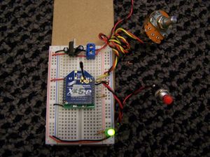
Input Module with Potentiometer and Switch
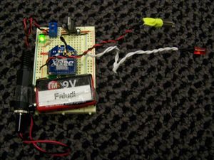
Output Module with Vibrator Motor and LED
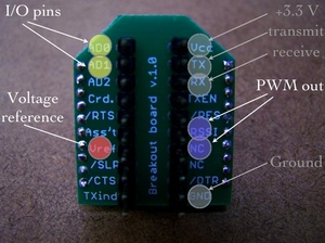
Connecting VREF to your supply is always recommended, though with digital inputs it will sometimes work without doing that. For a digital switch, the normal circuit is to either attach to the pin and ground (there’s an internal pull-up) or attach to the pin and power, adding a pull-down resistor to ground.
Hi,
Can i connect a Analog Joystick Directly to one of XBEE Znet module and control the 3 servos at the other end ?
I read the comments and came to know that we need a controller at the Servos end !!!
Can you please guide me on this ?
Sounds doable, assuming your joystick puts out analog signals that vary between 0 and 1.2 volts.
Hi,
I am using XBee Pro Series 2 modules and had updated to latest firmware through X-CTU.
I would like to read the status of a motion sensor which is 1 or 0 on a remote XBee module A.
Then the status (digital signal 1 or 0) will be sent to trigger on an LED attached to another XBee module B.
I had configure one module as coordinator and another as router.
Could I done this by directly connecting the sensor and LED to the DIO pins of the modules? What are the configurations or physical connections needed?
I also have a PIC microcontroller ready to be used if required.
Thank you very much for your attention and really appreciate for your help.
Yes, you can directly connect the sensors but you will need a microcontroller on the Series 2 hardware because direct pin-to-pin triggering is not available. Read the sensor with API mode and use the microcontroller to determine the state of the LED.
Hi,
So I set the modules to API mode
but how is the module A determine which of it’s pin is connected to sensor to be monitor and send signal over to module B?
and microcontroller connect to which pins of module B and process the signal to trigger the LED?
Thank you for your patience if I am asking a fundamental question as I am very new to XBee
Okay.. I will check the output voltages of my Joystick & come back to you..
How easy is it for one XBee module to recieve data from 2 other modules?
Hello Sir..
Iam a new student to you….
I brought Two XB24 type Xbe modules, one Xbee USB explorer from sparkfun, One Xbee explorer from spark fun, and a mini USB cable..
I have down loaded the XCTU software from Digi and installed
The Xbee radios are being detected by the software
I want test the connectivity between the two radios one connected to PC connected to USB explorer and other mounted on the Xbee explorer board…
Please suggest me the procedure… Iam not able to understand the Modem configuration details specifically with the function type…
Please guide me sir…
Regards…
Hi faludi,
I recently purchased 8 XBee ZB modules, and I am aware of the differences in pin assignments between these modules and the XBee 802.15.4 ones. What modifications would I need to make to the ZB modules in order to get direct I/O with ADC?
Best regards,
L
Direct I/O is not supported on the Series 2 / ZB hardware.
Hi faludi,
So the Series 2/ZB hardware will need to use microcontrollers?
L
At least one end of the communication will need an external microcontroller, or you could use the new programmable XBees.
One of the XBees is actually embedded in a ConnectPort gateway, on which Python programs can be uploaded. Will this work?
Yes, the ConnectPort includes controls that are external to the radio.
Thanks, faludi!
Hi Faludi,
I’ve xbee PKG Pro modem connected to PC through USB (host) and also xBee pro (end). Can i get and display analog signal through x-CTU since my end device has analog input. if so, how to setup the x-ctu to receive/display the analog signal
You can look at local analog signals with remote AT commands. These must be issued in API mode, which is possible but quite awkward though X-CTU. It’s much easier to issue the commands using a library. Here’s one for Java and another for Python.
Hi Mr. Faludi
I have connected an LM35 to a XBee, with its Vref to 3.3V. The module is Tx to my coordinator and i am recieving values on XCTU terminal. My problem is that the values in .hex format are very incosistent; that is, they present a high volatility.
Here are some examples for temperature reading:
5F
5B
5A
59
65
I have decided to take more samples and average the value, because i have to show them on an LCD which is attached to the coordinator.
My question basically is, why are these values so apart? I have checked and re-checked why this would happen (interference, heat source nearby, etc.) but have failed to understand to pin point the problem. Is the XBEE’s ADC that imprecise? Is there a work-around?
Thanks for your feedback.
Have you tried taking a voltage reading to see if the ADC is simply recording the correct values?
Sir,
This isnt exactly a reply, but another query, I am trying to do a similar thing instead of LM35 am using a pot, but am not getting anything on the XCTU terminal,
I have checked the adresses properly and have configured the IO pins and the XBEE’s are working fine when both are connected to PC and typing in one terminal is copied in the other… but with the Analog Data they dont seem to work, am not getting any output in the Terminal
That may be the case. However i am more inclined to say that it is because there is no signal conditioning. I have connected the output of the LM35 directly to the xbee ADC. Perhaps some filtering is in order…
Hey wil! I’m trying to do exactly the same thing. Just getting temp from a LM35 and send it directly to computer. I can’t read an accurate data from XCTU’s terminal window! Could you send me your circuit diagram and also did u get reasonable voltage value in hex on ur X-CTU’s terminal window? I’m getting non-sense data all in hex which i think they are just bunch of codes in hex not voltage values! 🙁 please help thanks
Data is delivered in API frames that need to be decoded, typically using a library. See the API section of the Product manual for your radio, or Chapter 5 of my book for more information on the XBee API.
Thank you very much for this document. But i could not view the pdf, also am presently working on XBee 24 version 10CD, i want to use the internal ADC.
Am facing problem wiring up the XBee at the remote (connecting the batteries to the XBee and also the voltage measurements from solar panel to the XBee). I have been able to get them see each other.
Please can you send a well detailed circuit layout of your
work. I will be thankful.
I’m using XBEE_PRO_SERIE2. (XBP24-B)
I can not establish a communication mode in AT. API only !!!!!
Please help me in detail. I’m new to the XBee …
TANKS
Use X-CTU to change to the AT firmware.
I have an LM19 sensor attached to an Analog XBee pin. The Sensor output is around 900 mV (below 1.1V, XBee maximum) and the measure i get is always 1024. I can’t make it more little than this value. Does this make sense?
Fixed. I’ve enabled pullup resistors (PR command) and improved my LM19 circuit adding a couple of capacitors. Seems to work right now 🙂
got an idea about how many mV does XBee consider as a 0 and how many as a 1?? i mean when digital sampling..
Sir, I want to establish radio communication between two xBees
for use in R/C Airplane. Which xBee module should be used and
what extra things do i require (like, only Microcontroller or the Arduino)?
I need to control it with two joysticks… How will the joystick data
travel from ground xBee to xBee on the plane??
hey faludi,
i have 3 xbees series 1. what i want to do is when i put voltage in a designated pin in xbee 1, i want it to transmit to xbee 2 and xbee 3 giving me a high on a pin, and when a designated pin in xbee 2 gets voltage, to transmit to xbee 1 and xbee 3 giving me high on a pin, and when a designated pin in xbee 3 goes high, to transmit to xbee 1 and xbee 2, giving me a high on a pin.
i tried to play around with X-CTU, but i was not able to get it to work.
do you have any suggestions on what i can do?
thanks
This seems possible with the Series 1. All the radios need to be set their destination address to broadcast (ATDL FFFF). Next you would have a specific pin set as an input on the transmitting radio (for example ATD0 3) and as an output on the receiving radios (similarly, ATD0 4). All the radios would need to accept I/O from any transmitter (ATIA FFFF). The trick is that each transmitting and receiving combination would need to use different pins. So XBee 1 would use Digital Input pin 0, XBee 2 would use Digital Input pin 1, XBee 3 would use Digital Input pin 2. Then the receiving radios would set the corresponding outputs, for example XBee 2 would use Digital Outputs 0 and 2. Naturally there might be some additional complexity to making this function properly—I haven’t personally attempted it—but certainly worth a try.
greetings sir, i recently purchased an xbee starter kit. xb24-dks-int. can i also use these modules to do the same task like what you do?
i wanted to use one module as a transmitter and one as a receiver. can i use the xbee so that when i input a digital input on a pin on the transmitter, i receive the same digital output on the same pin on thr receiver.
On the Series 1 802.15.4 XBees, yes.
Hi, if I wanna use the XBees to transmit some square waves, will direct i/o line passing work?
Its frequency is 38khz
I/O line passing would probably not be a good way to do this.
Hi, is it possible to do the same (one module as a digital input – on D1 for example, and the other one as a digital output D1 as well) using xbee series 2?
No, the ZB firmware on the Series 2 does not directly accept changes via line passing. You need to use API packets which means that a microcontroller must be at one end of the interaction (or you could use the new programmable XBees). My book has more info on this, by the way.
Thanks for the prompt response.
I’ve just read the API chapter of your book. It’s said that to turn a led on (on the romantic lightning sensor example) the AT cmd is 0x17, using the desired I/O (D1, for example) as Command name, and choosing between 0x4 and 0x5 to turn it on/off.
By doing that, what in fact is happening is the modification of the default state of the digital output.
Is it the right way to manipulate those variables?
Congratulations for you excellent book which is really help me with my final project with zigbee at university.
Hi, i would like to interface my PIC microcontroller with the ZigBee chip. As PIC operates on 5V and 3.3V for the Zigbee, do i need any voltage levelling circuits from my TX and RX output of my microcontroller before entering Zigbee? Can i connect my TX and RX straight to the Zigbee? Thanks
sorry, i forgot to mention in the above comment that i’m using Xbee 802.15.4. Sorry and thanks again
Check this information about XBee level-shifting.
thanks =)
I am converting a wired analog system to wireless and think that XBee may be the way to go. I am not a programmer so am looking for simple ways to get the data from the XBee network into Excel. All the popular methods use X-
CTU but I would like to take this data, place it in a text file and then continuously read it with Excel. There is no problem in reading the text files with EXCEL, but I cannot figure out how to get the analog data from the USB coordinator into a file. Constantly using the keyboard to save channel data is not an option. I do not want to take time to become a C Java or Python programmer. Any suggestions?
There’s not enough info in what you wrote so far to make a specific recommendation but you might want to consider the XBee Internet Gateway and it would definitely help to take a look through my book as well. There’s plenty of examples out there which will not require you to learn programming (though that’s certainly a helpful skill which I recommend!).
Hello, you can do with z24-b Series 2 ?????
The Series 2 ZB firmware does not support pin pairing so you need a computer or microcontroller on one end of the transaction. Then you can use API mode on one end to trigger direct output, or record direct input. Check Chapter 4 of my book for more information on this, including a full demonstration project.
Is the Xbee module compatible with a 6 bit delta-sigma ADC
sorry 16 bit
Depends what you mean by compatible. If your module puts out a TTL serial stream, then the XBee could probably handle it directly. Otherwise, if it’s I2C or something like that then you’d use a microcontroller to read the signal, and pass the information to the XBee in that way. Of course the XBee already has a 10-bit ADC built-in so if that resolution works for you you could skip the external ADC entirely.
Hello,
I’m having trouble with the ATD02 command… It always returns ERROR. I updated the firmware and ATVR returns 10EC.
Any idea ?
That should work. Check ATD12 and ATD03 to see if either of those give an error.
Yes they also do…
Hi.
Thank you for your help.
I use only digital communication(LED on/off).
I wonder whether this experiment is available for 1:N configuration or not.
I want to use 8 units for input module.
^-^
Direct I/O is 1:1 by pin, input can be accepted from many different XBees. Set the IA register to
FFFFto accept from any XBee.Dear faludi,
thanks for all your great tutorials.
i was hoping you can explain in detail the wiring of the
input module
– the resistors, and why you need them?
– the wiring of the components on the breadboard (i cant really tell it from the photo)?
– what should be the voltage range of the incoming data wire (e.g. the potentiometer)
i tried connecting a potentiometer to pin 0, but am getting garbage data. when i get my hand closer and away from the XBee, it seems like the wire i connected to the XBee pin from the potentiometer is serving as some sort of antenna and changing the values being read by the ADC, and i am not sure how to resolve that.
thanks!!!
One resistor is a pull-up for the switch. Another is the connection between power and VREF that’s required on the Series 1 hardware. Sounds like your potentiometer pin is floating. Make sure it’s attached to power, ground and the XBee.
Potentiometer goes to power, ground and the XBee’s physical pin 20 (AD0).
Switch goes to power, XBee physical pin 19 (AD1) with a 10K pull down resistor from AD1 to ground
thanks!
Hello Faludi,
Could you please suggest the available temperature sensors that can be used with the series 1 Xbee modules to make a wireless temperature sensor.
Try the TMP36. Here’s the instructions that go with my book for that sensor: http://www.faludi.com/bwsn/tmp36-instructions-simple-sensor-network/
hii faludi
i m working on same project. i have two Xbee XB24 10CD modules. i have set these parameter given by u.i want to ask do we have to set them as coordinator and end device?????
and can we take output on uart and io pins at the same time???
No for the Series 1 you don’t need to worry about coordinators. And yes you can have pin outputs and UART outputs simultaneously.
thanx 4 reply…i m set the parameters but what about rest of the parameters???
i have one modules XB24 10CD and 2nd is XB24 10E6….is there any problem with that?????
I’d recommend using the latest firmware versions, the same on both, but it is not required.
hiii faludi,
everything is working fine now….;-)
now i want to display the value of adc on PC(hyperterminal)…or is it possible to get value on digital io’s of output xbee module???
Sure. Check out the information on API mode in the Product manual or my book for parsing IO frames.
Would a xbee be appropriate for transmitting data to and from, say… a TI calculator?
Sure, if you can get the calculator to speak serial.
hi..
sir i want to configure 3 xbee n/w…2 xbee as the remote xbee & 1 as the base xbee at which i want 2 receive the data from 2 remote xbee. the remote xbee under ADC mode. how to set the address parameter of these xbee….plz rply..thnx in advance
Dear faludi,
I just want to get a temperature using lm35 and send it directly from Xbee pro s1 to my xbee receiver which is connected to my computer via USB. Which pin should i connect the lml35 to? and what is the command i can use in the Terminal window (x-ctu) to read from that pin? Thanks in advance
BTW i’m using 802.15.4, version 10E6. I have connected the output of the LM35 to PIN20 and I have set the D0 of the sender to 2 and the IU of the receiver to 1. AP is also set to 1. but on XCTU i get bunch of hex values that are non sense. Also when I use any AT command in terminal window it doesn’t change anything so I have to change the configurating by opening the modem configuration window. Please help! How can I get accurate temperature values?
hi sir,
i have two xbees XBP24, i wanna send analog signal from remote xbee to base one…i have set remote xbee pin d4 as analog i/p also set IT and IS commands but still i am not getting proper remote request command response frame. can u plz guide me on this?
Hello!
I have a problem triggering digital output (like DO0) on the remote ZigBee.
Case 1:
I know I can trigger it like this:
– setting digital input on the base ZigBee
– setting digital output on the remote ZigBee (DO LOW)
– and if configured right the input state on the base ZigBee is transferred to the digital output on remote ZigBee
I managed to do that, but I would like to trigger it via data packets.
Case 2:
So I tried with setting API packets that set the digital output on the remote ZigBee. I managed to change the digital output on remote ZigBee with commands ATD0=4 (DO LOW) ATD0=5 (DO HIGH).
DO LOW API command:
7E 00 10 17 05 00 13 A2 00 40 08 C9 80 00 02 02 44 30 04 21
DO HIGH API command:
7E 00 10 17 05 00 13 A2 00 40 08 C9 80 00 02 02 44 30 05 20
Problem:
But the problem I have is that sometime the communication between the base and remote might be lost. And if the digital output on the remote ZigBee is set to 3,3V (DO HIGH) and the communication is lost, the digital output would stay at the 3,3V. I want it to “reset” to 0V. In “case 1” when I tried to trigger the digital output with digital input, you can set the reset timer for that digital output (command ATT0) and it did the work (the digital input reset to value 0V), but you can’t use that in the case 2.
Question:
Does anybody know what is the API format of the packet to simulate case 1 – I/O line passing (case 1 data packets)?
Do you have any other ideas how to “reset” the digital output to 0V.
hai sir,
i bought 2 xbee s2 modules they are working well and i tried for sending digital data and configuring the remote with coordinator… they performed well and
i tried to change the MODEM CONFIGURATION from ZIGBEE ROUTER AT(22A0 version) to ZIGBEE ROUTER/END DEVICE SENSOR (2464 version).
now all are gone…. when i am trying to read the modem or test/query in xctu… the modem is not able to communicate and there is no response while i tried to read/write/restore…
there is a message displayed that to press the reset button and release ..i tried it tooo but the message box was not closing.
please send me info how to recover my modem…..?
thank u.
These instructions from DIY Drones often help.
thanks FALUDI it helped me a lot…..
i first used bootloader by typing B in the terminal as mentioned in digi
and then i read the remote device from my coordinator using modem configuration>open comport> discover
their i find my router and then i tried to load what i required it worked….
Hello there, I´ve read a lot of your experiments on the XBee and maybe you can help me with something new. I´m trying to control a 2 to 1 TX/RX serial mux. The thing is: the output side of the mux meets the serial port (TX/RX) of the remote Xbee and it must have a digital I/O pin to control the shifting on the mux. So the problem is: I need the serial port and 1 I/O pin to control the mux. As I´m studying, the Xbee modules can only work in TRANSPARENT MODE or API MODE, I´ve not heard about using the transparent mode and a I/O pin simultanelly. Do you know any way to do this? Since this moment I apreciate your attention. Thanks a lot.
You can use transparent mode along with the I/O features. You can control the pin either by using the I/O pin pairing on 802.15.4 (Series 1) radios, or Remote AT Commands on ZigBee (Series 2) and 802.15.4 radios. Remote AT Commands must be issued to the sending radio in API mode, but the receiving radio can be in transparent mode or API mode, it doesn’t matter.
Commands may also be sent over the Internet from iDigi.
See the discussion and chart on page 112 of my book for more info about API/AT mode being independent by node. Also more about I/O mode starting on page 87, and more about iDigi starting on page 204.
hi I’m new with xbee i want to read analog signal direct from xbee how can i do this please tell me with details because i new
thanks
Hi,
may i know why once i supply 3.3V to pin 1 and GND to pin10 then all the DIO pin got 3.3V?
how can i configure to make all DIO to become 0V? thanks
If this is the 802.15.4 module, did you connect the VREF pin?
Hi,
I have Series 1 Xbee modules and using the IO line passing to measure hall sensor signal. This hall sensor is used to measure the wheel speed and I want to count pulses on the receiver output.
I am not clear with settings IC and Tn.
Is it appropriate to use change detect only with IR disabled? Does Tn (T0, T1, T2 in my case) limit the frequency at which I can count pulses on receiver?
This is what I find,
With setting D0 = 3, IR = 0, IC = FF (on transmitter) I expect it to transmit when input changes (goes low).
On the receiver side DO = 5. When T0 = FF the output goes low immediately with change in input but takes 25 sec to go back high again. And when T0 = 0x1 the output is unstable (sometimes indefinitley low), but I expected it to go back high in (0x1 * 100)ms.
ATTn is used to time out output signals. With it set to 0xFF you are seeing the correct behavior. With it set to 0x1 you should see it go low very quickly but mostly be high. What firmware version are you using? And what happens if you set it to something like 0xA or 0x14 for a longer but still somewhat fast timeout?
IC will send a sample any time the digital pins indicated change from high to low or low to high. It can be used in conjunction with IR if you want to but that’s not required (or desirable in many cases).
Thanks for the reply. Firmware version I have is 10EC.
I prefer to use IC with IR = 0 as I want transmission only when input changes (from high to low and low to high).
Something with the timer does not work as expected. I felt the timer Tn does not start with first high to low pulse the receiver receives but starts when the input goes back from low to high. Because of this the output follows the input only on the first transition and not thereafter.
With everything set correctly is it right to expect that the output follows the input at same rate?
It is right to expect that. I’d recommend contacting Digi’s support, especially if you think you have a reproducible bug that they can fix in a future firmware upgrade.
Hey Faludi…
Thanks for posting some good info about the Xbee’s.
Since you are using these radio devices standalone, what is the power that you are supplying for optimal operation. I think Vcc regulated to 3.3V but what about the current ?
What are the different ways to power up the Xbee ?
Different models of XBee use different amounts of current. Regular power ones typically pull around 50mA. Higher power and WiFi can pull up to around 300mA. If we’re not using mains power, we often use LiPo batteries which the XBee seems to work quite well with directly.